Bill of material:
4 pcs. enammelled copper wire (CuL) diameter 2.0mm, length 0.3m each.
1 pcs. 22 pF 3kV SMD 1812 capacitor
2 pcs. 15 pF 3kV SMD 1812 capacitor
15 pcs. 10 pF 3kV SMD 1812 capacitor
Note: streching small coils made of 2mm wire needs a lot of strength. Pay attention to your fingernails ! Better to use some none metallic tools.
L6 and L19, air coils:
The inner diameter of this coil is 13mm, the real diameter 15mm and the outer diameter 17mm.
Wind 5 turns and strech the coil to a length of 15mm. The resulting air coil will have an inductance of 0.21uH. Check with an LC meter, the tolerance is 0.2 to 0.22 uH. If required, strech or compress the windings.
L24 and L25, air coils:
The inner diameter of this coil is 11.5mm, the real diameter 13.5mm and the outer diameter 15.5mm.
Wind 3 turns and strech the coil to a length of 10mm. The resulting air coil will have an inductance of 0.1uH. Check with an LC meter, the tolerance is 0.09 to 0.11 uH. Usually you will need to strech or compress this coil since it is nearly impossible to hit the right inductance at the first try.
22pF ... C26
15pF ... C68,84
10pF ... C81,82,62,63,66,85,22,23,24,25,29,30,58,59,83
With higher frequencies ist gets hard to match simulation and reality. Therefore I will not show the simulation above 10 MHz. Here are the real measured values from the fine tuned filter using above values:
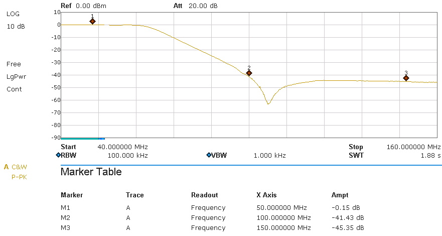
The passband attenuation of -0.15dB is a good value at these frequencies and shows that copper wire is still OK instead of the expensive silver wire. When transmitting with 1kW we have a loss of only 34 watts due to the -0.15dB.
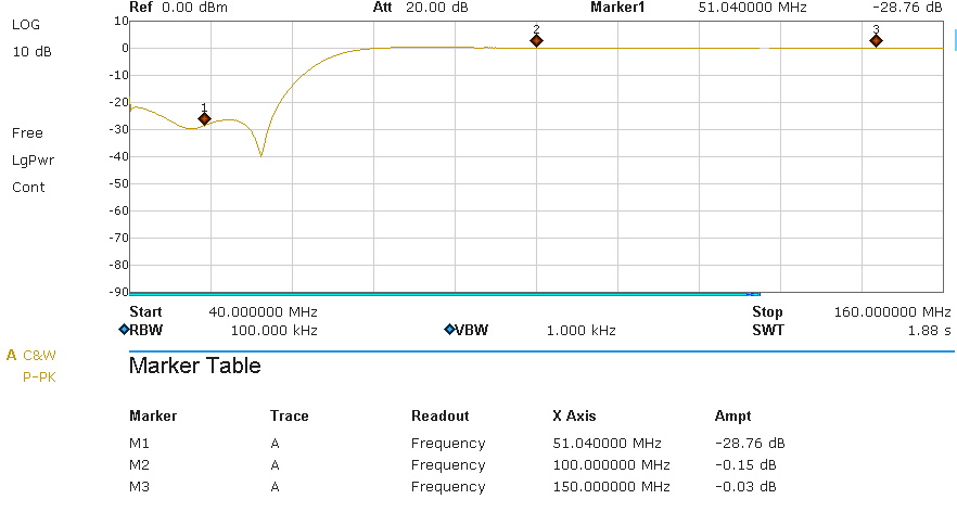
This is the reflection attenuation. -28 dB corresponds to an SWR of 1,08 : 1. When transmitting with 1kW a power of 1,5 watts will be reflected back to the amp.
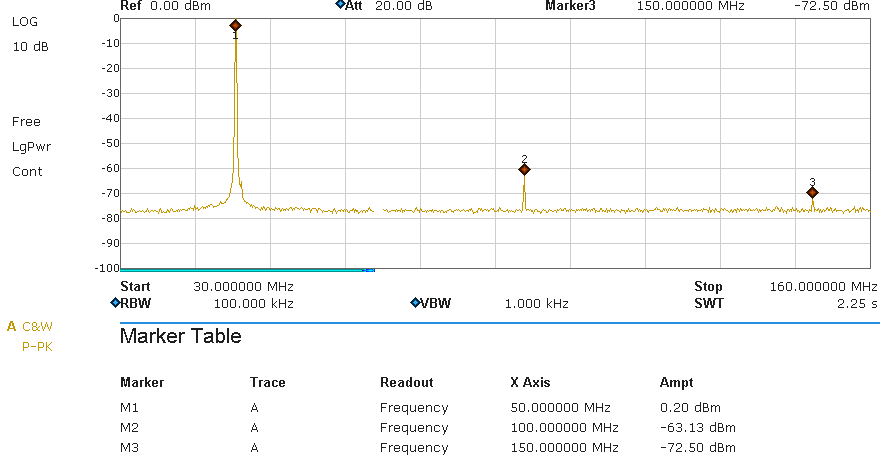
Results:
this picture shows the spectrum on a 50 ohms dummy load. The filter was driven by a Helitron.de LDMOS amplifier running at 1kW output power. A HP-attenuator was used to adjust the output to about 0 dB (The value at marker M1 is NOT the passband attenuation, it is just the 0-reference for this graph). The readings for the harmonics are the filter attenuation. The legal limit is -60dB (BNetzA 33/2007 and FCC 97.307). This requrement is fulfilled.