Bill of material:
4 pcs. enammelled copper wire (CuL) diameter 2.0mm, length 0.5m each.
13 pcs. 22 pF 3kV SMD 1812 capacitor
2 pcs. 15 pF 3kV SMD 1812 capacitor
4 pcs. 10 pF 3kV SMD 1812 capacitor
L2 and L3, air coils:
The inner diameter of this coil is 19mm, the real diameter 21mm and the outer diameter 23mm.
Wind 5 turns and strech the coil to a length of 20mm. The resulting air coil will have an inductance of 0.35uH. Check with an LC meter, the tolerance is 0.3 to 0.4 uH. If required, strech or compress the windings.
L1 and L11, air coils:
The inner diameter of this coil is 10mm, the real diameter 12mm and the outer diameter 14mm.
Wind 5 turns and strech the coil to a length of 15mm. The resulting air coil will have an inductance of 0.15uH. Check with an LC meter, the tolerance is 0.14 to 0.16 uH. Because this coil is small and has a few windigns only, it will usually be required to strech or compress the windings to get the correct inductance. Take care on the right distance of the connections of 15mm.
The real value of these inductors in not 0.12uH, it is 0.16uH. But we need a coil with 0.12uH because the rest of 0.04uH is provided by the PCB traces and the relais.
22pF ... C74,73,69,70,61,60,1,2,3,75,76,77,78
15pF ... C71,79
10pF ... C72,27,28,80
With higher frequencies ist gets hard to match simulation and reality. Therefore I will not show the simulation above 10 MHz. Here are the real measured values from the fine tuned filter using above values:
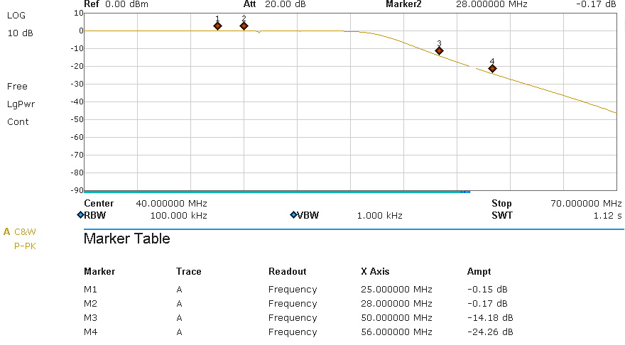
The passband attenuation of -0.15dB is a good value at these frequencies and shows that copper wire is still OK instead of the expensive silver wire. When transmitting with 1kW we have a loss of only 34 watts due to the -0.15dB.
There is a tiny drop right of marker-2 (at 30 MHz). This is a resonance from the 17/15m filter which is switched off during this measurement. The 17/15m filter was designed to keep this little drop above 30 MHz.
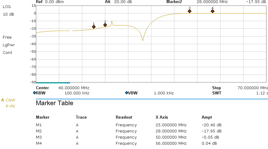
This is the reflection attenuation. We can see the resonance from the 17/15m filter, which can be ignored since it was shiftet to >30 MHz..
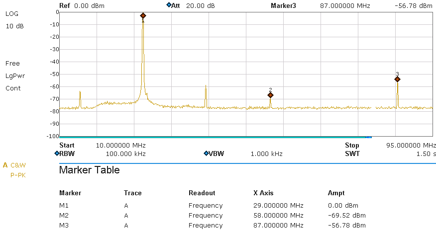
Results:
this picture shows the spectrum on a 50 ohms dummy load. The filter was driven by a Helitron.de LDMOS amplifier running at 1kW output power. A HP-attenuator was used to adjust the output to about 0 dB (The value at marker M1 is NOT the passband attenuation, its just the 0-reference for this graph). The readings for the harmonics are the filter attenuation. The legal limit is -40dB (BNetzA 33/2007) and in USA (FCC 97.307) -43 dB. This requrement is fulfilled.
10m: