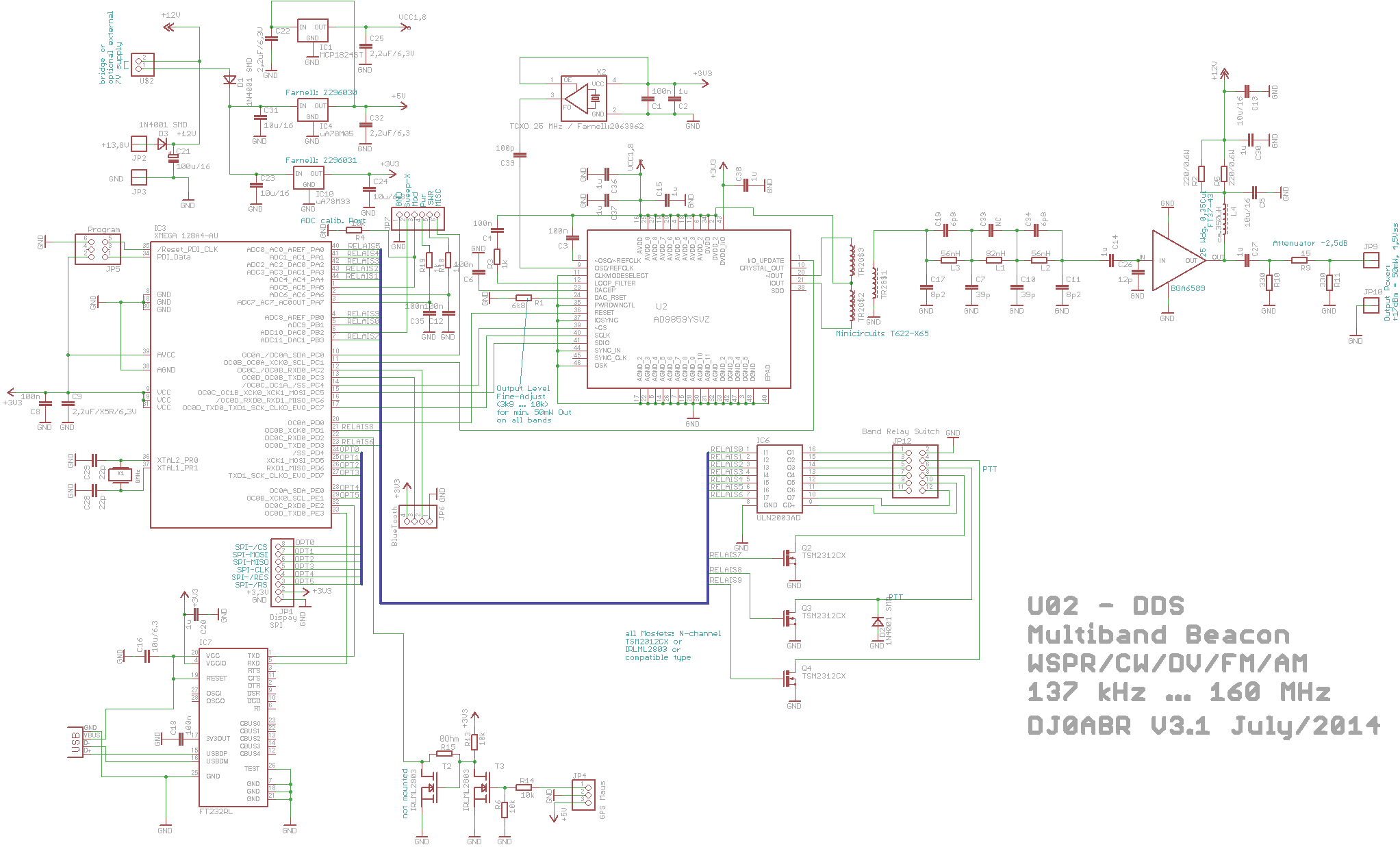
The heart of this board is a DDS synthesizer, the Analog Devices AD9859, which creates an output frequency from 0.1 to 160 MHz. It is controlled by a ATxMega128AU Micro controller which programs the frequency and via software creates the FM, AM and CW test signals.
As a special feature a complete WSPR beacon is included that conforms to the original K1JT protocol. Therefore WSPR operation can be performed on all bands from long wave up to 2 meters.
The board has outputs for Band Relays of a suitable power amplifier, which is also detailed below.
The original idea for the board was born in our Radio Club by the desire to participate in medium wave (474.2 kHz) in WSPR. With no commercial equipment available we decided to build our own. This approach provided such good results that now all 13 bands up to 2m can be covered. The WSPR synchronisation is accomplished with a GPS mouse, thus for the first time mobile WSPR operation is possible with automatic update of the position!
The frequency accuracy is 2ppm using a temperature compensated crystal oscillator (TCXO).
Overview:
The DDS Synthesizer operates free standing. Only to configure it a PC is connected via USB. Once configured the PC is no longer required. However it can stay connected and be utilized as a monitor or to make manual changes during operation.
The AD9859 can create any wanted frequency from DC to 200 MHz. The lower limit is set by Ferrite transfer and is around 100 kHz. The complete WSPR protocol is included and the board can transmit as an autonomous WSPR beacon (without a PC). The time synchronization is performed with a GPS mouse. The output power is 50 mW, enough for intercontinental connections. With the 5 W amplifier all continents can be reached on a daily basis.
Beacon Mode: Beacons for different modulation schemes are included. In addition to the WSPR mode the board can also operate as a CW beacon with automatic power regulation for different level beacon transmissions. Additionally a D-Star beacon is available to conduct test and analysis from a variety of potential repeater locations to evaluate the coverage areas.
Synthesizer operation: If one has a DDS - one might as well expand it to a signal generator. Therefore the board includes functions for FM and AM modulation with specifiable parameters as well as a sweep frequency signal generator. This could be used for experimentation with filters. The frequency range is tunable in a wide range.
Diagram: (to resize click on it)
Complete Bill of Material see
HERE.
The AD9859 DDS Synthesizer is controlled by an ATMEL Microcontroller. It is triggered by an 8 MHz SPI bus to enable a quick change of frequency. This allows FM modulation and sweep frequency signal generation. Three voltage regulators are present. 3.3 V for the processor unit, 1.8 V for the DDS Synthesizer and 5 V for the operation of the GPS mouse.
The USB connection was accomplished with a FT232RL chip creating a virtual serial connection. The availability of both Windows and Linux drivers for this chip made it a comfortable solution. If one wants to get away without using a PC altogether, one can also configure the DDS with an Android smartphone via Bluetooth. This allows for example to select the WSPR bands, adjust the transmit power etc. We use a reasonable priced Bluetooth module available on the market.
The push-pull output of the AD9859 is decoupled with a 1:1:1 transformer by Minicircuits. This provides a 6 db advantage vs. resistive solutions. Following the core is the very important output filter which has to cut of everything above the clock frequency. Without such an effective filter the operation would not be possible as unwanted spurious emissions would be created. However with this filter one can achieve close to -50 dB signal to noise ratio near the useable frequency and even -70 dB further away, which is good enough for short wave applications.
The output signal is increased with a MMIC amplifier to 100 mW. To prevent overdriving the amp a PI-attenuator is used. This reduces the output power to 50 mW but prevents mismatching which is important when used as a test instrument.
Furthermore the design includes 8 open collector outputs to control relays as well as a PTT output. This socket can be connected with a ribbon cable directly with the same socket on the 5W amplifier to perform automatic band switching. The PTT line also ensures that the PA quiescent current of the amp is turned of when not in transmit mode.
And finally we have an input for a GPS mouse. This input is also configurable in order to utilize mice with 5V or 12V levels.
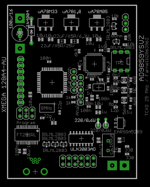
The board:
this is the part placement:
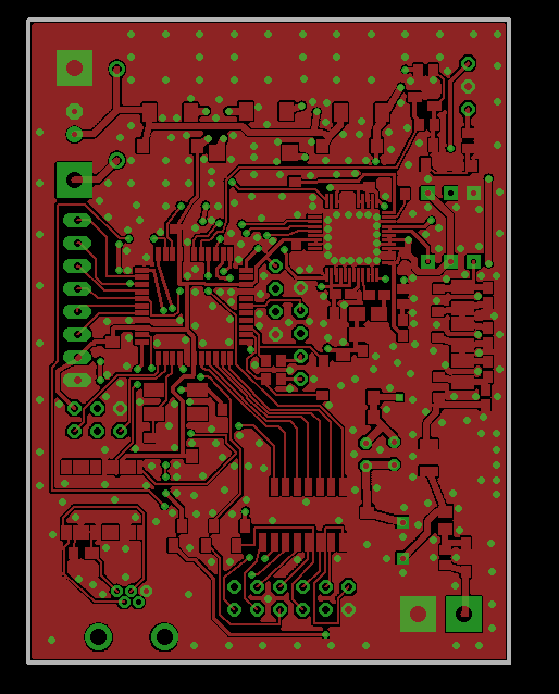
and the layout of the top side:
Assembly:
The assembly of the board is doable even manually with proper tools. However it is not a job for folks new to SMD soldering. One can’t have any hesitation about the small size components. Therefore boards will be available that are already assembled and programmed for those who prefer not to solder SMDs.
A detailed description on how to assemble the board won’t be provided - as I believe only those that know how to do it should try it.
Start-up procedure:
Use a power supply that can be voltage regulated and start at zero volts and limit the current to 250 mA. Now slowly bring up the voltage and continuously check the output voltage on the three regulators (1.8 3.3 and 5 V). These voltages may not exceed the planned 1.8 3.3 and 5V. If the result is OK one can now feed the usual 13.8V to the board.
Next connect a PC to the USB port. If using LINUX the drivers are already available. With Windows the drivers will automatically install. Afterwards start the PS Software “wsprset.exe”. If using LINUX precede this with the installation of the package ‘mono”.
The software is self-describing - one completes the various input fields and clicks “SET” to send the commands to the board - done. After connecting a proper antenna or a 50 Ohm dummy load the synthesizer can be started either in WSPR mode or as a signal generator or sweep frequency generator.
WSPR Operation:
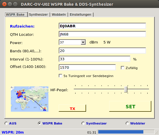
First enter the call sign and QTH locators first 4 digits, select the power level (if not using an amplifier this is 17 dBm. Then enter the wanted bands as a list, comma delimited. e.g. 630,160,80,40, or 20,15,10 etc.
The transmit interval defines how often the board transmits and how long a pause is in-between. In WSPR a common value is 33% to the be exceeded. Only with very small power levels or smaller than 200 mW one can go higher to 50% or more.
Offset provides the selection of the transmit frequency within the WSPR band and inputs from 1400 to 16000 are possible.
The slider HF Pegel is used to adjust the actual output power from 0 to mac power. This should agree with the value mentioned above. (check with oscillator).
After all values have been entered push the SET button. The data will now be permanently stored on the board. Now click on WSPR beacon (Bake) and the operation starts. From this moment on it makes no difference wether or not a PC is connected - it would only serve as a monitor. The board functions autonomously.
ATTENTION: WSPR operation is only possible with a connected GPS mouse that provides an accurate time signal. Without a GPS signal the WSPR transmitter will not start. For the time signal even a weak GPS signal will suffice (like near a window) even if no navigation solution can be provided.
Frequency Adjustment:
The reference crystal is a highly accurate TCXO which comes already tuned to 2ppm.
Extremists can adjust the reference crystal on the board to an accuracy of 0.1 Hz. To do that on activates the board for a quarter of an hour to achieve the proper temperature. Then use the synthesizer mode and enter a frequency of 10 MHz and press SET. Now compare the signal utilizing a SSB receiver and compare the signals from WWV and the generator for zero beat.
The window “SETUP” allows entering a value that brings the beat to zero. Usually values between -20 and +20 are needed. The firmware analyzes these values two digits after the decimal point. In the Beta unit i had to enter 0.6 for example in oder to rech 0.1 Hz. Once done this value stays the same for the complete bandwidth from 100 kHz to 150 MHz.
Synthesizer:
In synthesizer mode any desired frequency between 100 Hz and 160 MHz can be created with 1 Hz steps.The accuracy if aligned is also 1 Hz. The output power can be adjusted between 0 and 50 mW (at 50 Ohm).
FM modulator:
The fundamental frequency can be modulated with a selectable audio frequency. The maximum is 5 KHz. The deviation is adjustable in a wide range with 1 Hz steps. The FM modulation is done by software and continuously reprogramming the audio frequency..
AM modulator:
The fundamental frequency is being amplitude modulated and the values adjustable from 0 to 100%.
AM and FM modulation can be performed simultaneously. However I question if this makes much sense - but it works.
Sweeper:
In sweep mode any frequency range between 100 KHz and 160 MHz can be defined with an adjustable speed. (saw tooth)
Example: to measure the bandwidth of a receiver filter one specifies 14.100 to 14.105 with a speed of 1000 ms. This sweeps an area of 5 KHz. The sound in the receiver is similar to a gambling hall in Las Vegas but it works well to look at the filter curve on a scope.
To check a HF transmitter low pass filter one specifies for example 1 MHz to 30 MHz in 5000 ms speed.
ny other values wanted can be entered of course.
An analogue output signal representing the frequency will be created. This is connected to the X input of the Oscilloscope the create a clean and stabile image.
Connectors:
these are the various connectors on the DDS board:
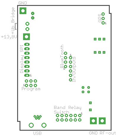
GPS:
1 ... serial Input from the GPS mouse
2 ... GND
3 ... +5V for the GPS mouse
Display SPI:
1 ... GND
2 ... +3,3V
3 ... RS (Control/Data)
4 ... /Reset
5 ... Clock
6 ... MISO
7 ... MOSI
8 ... /CS Chip Select
BlueTooth:
1 ... GND
2 ... ser. data from BT module
3 ... ser. data to BT module
4 ... +3,3V
In-/Outputs:
1 ... GND
2 ... Sweep Output for X-axis of an oscilloscope
3 ... LF Input, modulation signal
4 ... Input from PwrSwr board: FORWARD-line
5 ... Input from dr PwrSwr board: REVERSE-line
6 ... aditional digital port for future developments
Program:
Connector for Atmel Programmer PDI mode
+Ub Brigde:
there are two options:
1) bridge (short cut): the complete board is supplied withthe +13,8 volts power supply
2) open, the upper pin is connected to a 7-8 volts / 500mA power supply. This will be used to supply the DDS logic. The output amp is supplied with the 13,8 volts. The advantage is a lower power consumption of the board if the 7v power is generated i.e. with a DCDC converter.